Table of Contents
- 1 Introduction
- 1.1 Mistake #1: Treating Thermal Management as an Afterthought
- 1.2 Mistake #2: Under-Specifying the Power Supply
- 1.3 Mistake #3: Neglecting Beam Delivery and Alignment
- 1.4 Mistake #4: Choosing the Wrong Wavelength for the Application
- 1.5 Mistake #5: Overlooking Laser Safety Compliance
- 1.6 Mistake #6: Inadequate Cooling for Optical Components
- 1.7 Mistake #7: Poor Vibration and Mechanical Stability
- 1.8 Mistake #8: Misunderstanding M² and Beam Quality
- 1.9 Mistake #9: Failing to Plan for Maintenance and Serviceability
- 1.10 Mistake #10: Underestimating Control System Integration
- 1.11 Conclusion: Design for Success from the Start
Introduction
You’ve spent months on the design. The prototypes are built, and the moment of truth arrives. You power on the laser system, only to be met with unstable output, thermal drift, or worse, a catastrophic failure. The project timeline stretches, the budget evaporates, and the frustration mounts.
This scenario is more common than you might think. Laser system design sits at the crossroads of optics, electronics, thermal dynamics, and mechanical engineering. A minor oversight in any one of these disciplines can lead to major performance issues down the line.
The good news? The most common laser system design mistakes are predictable and, therefore, avoidable. After years in the field, we’ve seen patterns emerge. In this post, we’ll dissect the top 10 laser system design pitfalls that sabotage performance, reliability, and your bottom line. More importantly, we’ll provide actionable engineering strategies to avoid them, ensuring your next system is robust, efficient, and successful from the first power-on.
Mistake #1: Treating Thermal Management as an Afterthought
The Mistake: Perhaps the most pervasive error in laser design is failing to prioritize thermal management from the very beginning. This isn’t just about the laser source itself; it includes diodes, amplifiers, optics, and even electronics. Many designers specify a chiller late in the design process, without a full thermal analysis of the entire system.1
The Consequences: Heat is the enemy of precision. Inadequate thermal control leads to:
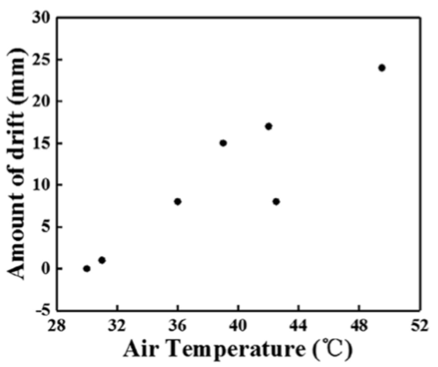
- Wavelength Drift: The output wavelength of many lasers (especially diodes) is highly temperature-dependent.2
- Power Instability: As components heat up, their efficiency drops, leading to inconsistent output power.
- Reduced Lifetime: Every 10°C increase in operating temperature can approximately halve the lifetime of laser diodes and other optoelectronics.
- Beam Pointing Instability: The physical expansion and contraction of mounts and bases can cause the beam to “walk,” misaligning your entire system.
The Solution:
- Start Early: Integrate thermal analysis into your initial CAD models. Use simulation tools to identify hot spots.
- Specify Properly: Don’t just pick a chiller with enough cooling capacity. Consider flow rate, pressure drop, temperature stability (±0.1°C is often necessary), and compatibility with your coolant.
- Think Holistically: Actively cool critical optics in the beam path. Use thermally conductive, stable materials like copper or invar for mounts, and consider thermoelectric coolers (TECs) for precise, localized temperature control of sensitive components like laser diodes.
Mistake #2: Under-Specifying the Power Supply
The Mistake: Viewing the power supply as a simple commodity component, leading to selection based solely on output voltage and current. This ignores critical factors like noise, stability, and transient response.
The Consequences:
- Output Noise & Instability: Ripple and noise from the power supply are directly transferred to the laser’s output, causing intensity noise and mode instability.
- Premature Failure: In-rush current at startup can stress laser diodes beyond their limits. Voltage spikes can cause arc-overs in high-power systems.
- Inconsistent Performance: A power supply that can’t maintain regulation under dynamic load conditions will lead to unpredictable laser behavior.
The Solution:
- Demand Detailed Specs: Look beyond the headline numbers. Scrutinize the datasheet for line and load regulation, output ripple & noise (in mVpp), and transient response time.
- Match the Technology: Use low-noise, linear supplies for sensitive analog circuits and TECs. Ensure switch-mode supplies (SMPS) for main power have appropriate filtering and are kept away from sensitive analog areas on the PCB.
- Implement Soft-Start Circuits: Protect your laser diodes by designing or selecting a power supply that includes a proven soft-start mechanism to limit in-rush current.
Mistake #3: Neglecting Beam Delivery and Alignment
The Mistake: Designing a perfect laser source but giving no forethought to how the beam will be steered, focused, and delivered to the target chamber. This results in an “alignment nightmare” that is neither stable nor user-serviceable.
The Consequences:
- Impossible Alignment: The system cannot be aligned to specification, or it takes an expert days to do so.
- Daily Re-Alignment: The system is so sensitive that thermal cycles or minor vibrations knock it out of alignment, requiring constant maintenance.
- Loss of Beam Quality: Using the wrong mirrors or lenses introduces wavefront error, scatter, and loss.4
The Solution:
- Design for Kinematics: Use kinematic mounts (e.g., tip-tilt) for critical mirrors. These provide orthogonal, non-binding adjustment, making alignment intuitive and stable. See the basics of kinematic mirror mounts.
- Plan the Path: Use optical design software to model your beam path. Ensure you have sufficient and strategically placed beam steering mirrors to make the path achievable.
- Specify for the Wavelength: Choose optics with the correct coating for your laser’s wavelength and power level. For high-power systems, use reflective optics where possible to avoid thermal lensing in transmissive components.
Mistake #4: Choosing the Wrong Wavelength for the Application
The Mistake: Selecting a laser wavelength based on cost or familiarity without a rigorous analysis of its interaction with the target material or the requirements of the detection scheme.
The Consequences:
- Inefficient Processing: In materials processing, the wrong wavelength can lead to poor absorption, resulting in low processing speed, excessive heat-affected zones, or inability to ablate the material at all.
- Poor Signal-to-Noise Ratio: In scientific or measurement applications, the wrong wavelength can be overwhelmed by background radiation or fail to excite the target molecule effectively.
- Safety Complications: Unexpected wavelengths may require different (and more expensive) safety eyewear and interlocks.
The Solution:
- Understand Material Properties: Research the absorption spectrum of your target material. For example, metals absorb shorter wavelengths (e.g., 1µm) better, while many polymers are better processed with longer wavelengths (e.g., 10.6µm from a CO2 laser).
- Consider the Environment: For LIDAR or atmospheric sensing, choose wavelengths in the “atmospheric transmission windows” to avoid absorption by water vapor or CO2.
- Factor in Detection: If using a spectrometer or camera, ensure its sensitivity curve overlaps optimally with your laser wavelength and any resulting fluorescence or scattering.
Mistake #5: Overlooking Laser Safety Compliance
The Mistake: Treating safety as a final step—something to be “added on” before shipping. This is a critical legal and ethical error. Regulations (like FDA/CDRH in the US and IEC internationally, See the overview of IEC 60825-1 laser safety classes.) are complex and must be designed into the system from day one.
The Consequences:
- Legal Liability and Fines: Shipping a non-compliant system can result in massive fines, import/export holds, and product seizures.
- User Injury: The most severe consequence is causing serious eye or skin damage to an operator.
- Costly Redesign: Retrofitting safety features like interlocks, shrouds, and labels into a finished design is exponentially more expensive and difficult.
The Solution:
- Start with a Hazard Analysis: Classify your laser according to the relevant standards (e.g., IEC 60825-1) early in the design. This dictates all your safety requirements.
- “Design-In” Safety: Integrate redundant interlocks on all access panels, use embedded keys, and design robust protective housings (e.g., e-stops) from the outset. Ensure all labels are part of the mechanical CAD model.
- Document Everything: For your technical file, which is necessary for certification, carefully record your safety justification, risk assessment, and testing protocols.
- Avoiding laser system design mistakes also means baking compliance into the design, not bolting it on.
Mistake #6: Inadequate Cooling for Optical Components
The Mistake: Assuming that only the laser gain medium generates significant heat. High-power beams can rapidly heat lenses, mirrors, and windows, especially if they are absorbing even a small fraction of the power.5
The Consequences:
- Thermal Lensing: A heated lens changes refractive index and shape, acting as an unintended, dynamic lens that distorts the beam profile and ruins focus. Good primer on thermal lensing in high-power optics.
- Birefringence: Thermal stress in crystals (like those in Q-switches) induces birefringence, degrading polarization and efficiency.
- Coating Damage: Persistent heating can crack, delaminate, or burn optical coatings, leading to catastrophic failure.
The Solution:
- Use Low-Absorption Optics: Specify optics with exceptionally low absorption coefficients for your specific wavelength and power level.
- Actively Cool High-Power Optics: For mirrors and lenses in multi-kilowatt systems, use water-cooled optomechanical mounts.6
- Choose Materials Wisely: For transmissive optics, Fused Silica generally has a lower thermo-optic coefficient (dn/dT) than BK7, making it more resistant to thermal lensing. For reflective optics, copper substrates offer excellent thermal conductivity.
Mistake #7: Poor Vibration and Mechanical Stability
The Mistake: Designing a system with flimsy structural elements, thin-walled enclosures, and poorly chosen damping materials, assuming an “optical table” environment will always be available.
The Consequences:
- Beam Pointing Instability: The beam jitters and drifts, making precision applications like microscopy or direct-writing impossible.
- Premature Wear: Vibrations can loosen fasteners and cause microscopic fretting in mechanical contacts.
- Acoustic Coupling: External noise (e.g., from cooling compressors or factory floors) can be transmitted to optical components, causing high-frequency dither.
The Solution:
- Design a Stiff Structure: Use finite element analysis (FEA) to model and improve the natural frequency of your structure. A stiffer structure (higher natural frequency) is less susceptible to low-frequency environmental vibrations.
- Isolate Strategically: Incorporate passive or active vibration isolation systems at the interface between the machine and the floor. Use kinematic coupling principles for repeatable mounting.
- Dampen Internally: Apply constrained-layer damping materials to large, flat panels to reduce ringing and acoustic noise transmission.
Mistake #8: Misunderstanding M² and Beam Quality
The Mistake: Specifying a laser based solely on output power and wavelength, while ignoring the beam quality factor (M²). This is like buying a car based only on horsepower without considering the transmission and tires.
The Consequences:
- Inability to Focus: A laser with a poor M² (much greater than 1) cannot be focused to a small, high-intensity spot. This is disastrous for applications like cutting, welding, or nonlinear optics.
- Unexpected Divergence: The beam may spread out much faster than expected, losing useful intensity over distance.
- Wasted Power: You pay for watts of power that are unusable for your application because they can’t be delivered to a small enough area.
The Solution:
- Know Your Application’s Requirement: Calculate the required focused spot size and depth of focus. This will dictate the maximum M² you can tolerate.7
- Demand M² Data: Always require a verified M² measurement from the laser manufacturer. Do not accept “diffraction-limited” as a specification without a number (M² < 1.1 or 1.3 is typically considered diffraction-limited).8
- Understand the Trade-offs: Generally, higher power and specific laser types (like fibers) can offer excellent beam quality, but it’s not a given. It must be a key selection criterion. Check our Photonics Dynamics Laser optics Calculators A suite of powerful tools to assist with your laser system calculations and optical designs.9
Mistake #9: Failing to Plan for Maintenance and Serviceability
The Mistake: Designing a “black box” system where critical components like laser diodes, optics, and electronics are buried under layers of assembly, requiring complete disassembly for replacement or service.
The Consequences:
- Prolonged Downtime: A simple replacement that should take minutes turns into a day-long teardown and realignment.
- Introduction of New Errors: Every time the system is torn down and reassembled, you risk introducing new contamination, misalignment, or damage.
- High Service Costs: Field service becomes prohibitively expensive, damaging customer relationships and your product’s total cost of ownership.
The Solution:
- Design Modularly: Create sub-assemblies (e.g., “Laser Engine,” “Beam Delivery Unit”) that can be easily swapped out.
- Provide Clear Access: Design large access panels and use captive fasteners. Ensure that frequently serviced items (like fuses or filters) require no tools.
- Incorporate Service Aids: Include kinematic re-registration features for modules and built-in alignment tools like HeNe lasers or CCD beam profilers to streamline field service.
Mistake #10: Underestimating Control System Integration
The Mistake: Treating the laser as an island, with a poorly defined and unstable interface to the broader machine control system (e.g., PLC, PC). This leads to communication errors, timing jitter, and unreliable operation.
The Consequences:
- Communication Failures: Intermittent errors on a serial or Ethernet connection can cause the laser to behave unpredictably or shut down.
- Timing Jitter: Inadequate hardware triggering leads to inconsistent pulse timing in materials processing or data acquisition.
- System Complexity: The end-user is left with the difficult task of integrating disparate systems from different vendors.
The Solution:
- Define a Robust Interface: Use industry-standard communication protocols (EtherCAT, Profinet, etc.) where possible. For analog/digital I/O, use opto-isolation to prevent ground loops and noise.
- Use Hardware Triggers: For timing-critical tasks (<1ms), always use dedicated hardware trigger lines, not software commands.
- Develop a Clear API: Provide a well-documented software library (API) that allows the host system to easily and reliably control all laser functions.
By diagnosing laser system design mistakes early, you can cut rework and downtime.
Conclusion: Design for Success from the Start
Designing a high-performance laser system is a complex, multidisciplinary challenge. However, by being aware of these common risks, you may design solutions that ensure dependability, performance, and safety.
The main focus is comprehensive, integrated design. Do not have your thermal, optical, mechanical, and electrical engineers operate in silos. Encourage collaboration from the beginning, with safety and serviceability as basic concepts, not afterthoughts.
By avoiding these ten mistakes, you may transition from a cycle of troubleshooting and rework to a more efficient process of creating robust, successful laser systems that perform as intended, live longer, and satisfy your customers.
Get the checklist and eliminate laser system design mistakes before your next power-on.
Need Professional Design Review?
Our engineering team specializes in laser system optimization and risk mitigation.
📧 info@photonicsdynamics.com
🌐 www.photonicsdynamics.com
📞 (512) 920-2652
- Yang, Song, et al. “Automatic compensation of thermal drift of laser beam through thermal balancing based on different linear expansions of metals.” Results in Physics 13 (2019): 102201.
↩︎ - Chen, X. Sun, X. Li, L. Cai, D. Zhao, K. Du, M. Pan, M. Qiu, 4H-SiC Metalens: Mitigating Thermal Drift Effect in High-Power Laser Irradiation. Adv. Mater. 2024, 37, 2412414. https://doi.org/10.1002/adma.202412414
↩︎ - Yang, Song, et al. “Automatic compensation of thermal drift of laser beam through thermal balancing based on different linear expansions of metals.” Results in Physics 13 (2019): 102201. ↩︎
- https://www.edmundoptics.com/knowledge-center/application-notes/lasers/beam-quality-and-strehl-ratio/?srsltid=AfmBOoo9D7BDhZGassKt-8V9pFyiL6EsqVKe-Yk_mY78YCUKA7obUWOI ↩︎
- https://www.electrooptics.com/feature/red-hot-cooling ↩︎
- Why Water-Cooling is Critical for High-Power Laser Applications. https://en.gainlaser.com/case_detail/1856200467221594112.html ↩︎
- A. Siegman, “’Non-Gaussian’ Beam”, OSA Annual Meeting, Long Beach, CA (1997) ↩︎
- International Organization for Standardization. (2005). Lasers and laser-related equipment — Test methods for laser beam widths, divergence angles and beam propagation ratios — Part 1: Stigmatic and simple astigmatic beams (ISO 11146-1:2005). ↩︎
- https://photonicsdynamics.com/calculators ↩︎